Products and Services
Conventional drainage system
A conventional drainage system can be designed for large surface areas but does not cut off air flow into the pipe. For this reason pipes are sized for filling ratios of 20% or 33% (depending on national or local standards and regulations) allowing considerable amounts of air into the pipes of 80% or 67% of the pipe section.In conventional roof drainage, the outlets are simple “funnels” installed on the roof covering and connected to the downpipes which are as high as the building and the water collectors which require a gradient of at least 1%, are dimensioned for a maximum filling factor of 70%.
When the water collectors are very long and it is not possible to provide the minimum slope necessary due to the limited space available, the only solution is to increase the size of the pipes with a consequent rise in installation costs.
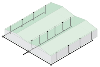
Rainplus® siphonic drainage system
The Rainplus® siphonic drainage system is made up of special outlets that incorporate an anti-vortex plate that prevents air entering into the pipes. The outlets are connected via short pipes of relatively small diameters to the horizontal water collector which is located just under the building roof. The collector pipe, generally installed at the highest possible position, runs horizontally (no fall angle is required) until it reaches connection with the downpipe. The downpipe drops into the drainage line which is buried in the ground and conveys the water straight into a collection tank or the municipal stormwater mains. The absence of air in the system allows it to run 100% full of water making use of the entire pipe section and vastly increasing flows that are 10 times faster when compared to conventional drainage systems.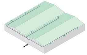
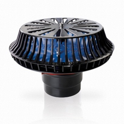
Outlet
One of the key elements of the system is the Rainplus® outlet that has been designed and manufactured to meet the requirements and testing criteria set by the international standards EN 1253 and ASME A112.6.9. • wide range of drainage flows (up to 65 l/s with Rainplus® 110 and up to 14 l/s with Rainplus® 56); • Reduced roof water levels required to trigger the siphonic action; • No swirls thanks to the special profile of the antivortex disk and reduced pressure losses at the inlet; • Low noise levels and maximum operation stability; • Easy installation thanks to the reduced number of components and compact size. For example, Rainplus® 56, in the version with horizontal connection, can be installed inside the roof slab thanks to a height of just 104 mm; • Connection with the Valsir HDPE system is extremely reliable; • Suitable for installation in gutters, even of small dimensions, or on roofs covered with any type of waterproofing material.HDPE
All Rainplus systems installed by CRS use Valsir HDPE pipe and a Rainplus specific bracketing system.
Valsir HDPE advantages
• Lightweight components providing easier installation
• Fast installation times saving labour costs
• Electrofusion coupling connections
Rainplus Bracketing advantages
• Simple pre-fabrication
• Easy installation without specialist tools
• Reduced amount of brackets
• Resistance of heat expansion and contraction
• Anchored to pipe and rail using high resistance bolts
Flow Stages

Stage 1
With a moderate flow, of 10 or 15% of the design rainfall intensity value, the roof outlet works as it would in a conventional system and the flow is defined “gravity flow”, in that air content in the pipes is elevated.
Stage 2
When the water discharged from the roof is between 10 to 15% and 60% of the full bore flow condition, water flow is discontinuous and the system therefore fluctuates from a gravitational flow regime to a full siphonic action. At these rainfall values the water that accumulates on the roof fills the outlet, cutting off air flow into the pipe and triggering the siphonic action. The velocity of water discharged therefore increases which results in falling water levels, allowing air to be drawn into the piping network and breaking the siphon; for this reason this stage is called “plug flow”.
Stage 3
When the water discharged is between 60% and 95% of the design rainfall intensity value, the pipes are completely full of water although many air bubbles are still present. This stage is called “bubble flow” and features high flow velocities thanks to the siphonic effect.